• Folks, if you've recently upgraded or renewed your annual club membership but it's still not active, please reach out to the BOD or a moderator. The PayPal system has a slight bug which it doesn't allow it to activate the account on it's own.

90g DIY LED w/ sunrise/sunset/moonlight

I have a similar post on Reef Central, but as a fellow 856er, I thought I would also post here.

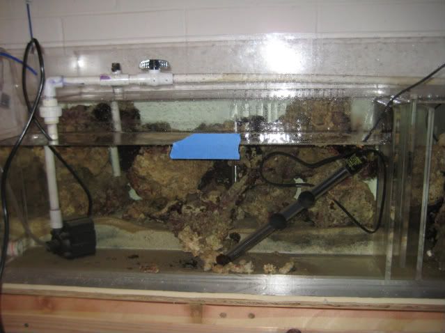
Currently I have a 90 gallon filled with air. It has moved 10 feet across the room to make space for my sump/refugium. But the delay has not been the tank or the sump, or convincing my wife that this was okay to do. The delay has been on the design and testing of the circuit.

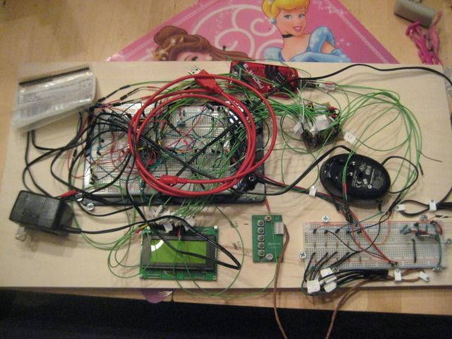
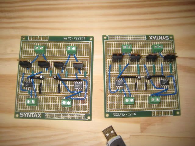
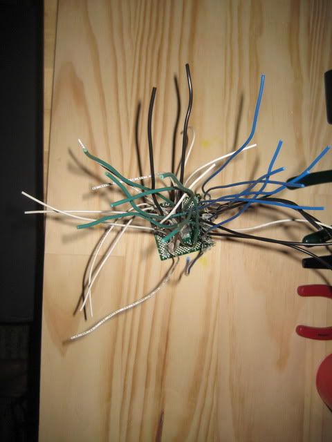
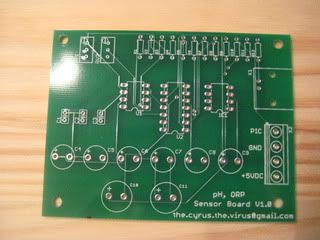
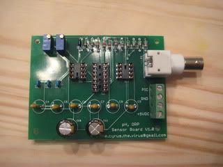
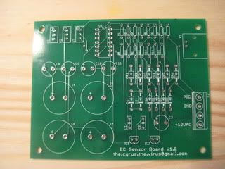
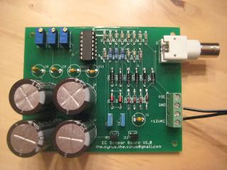
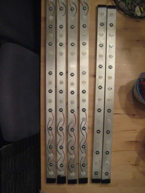
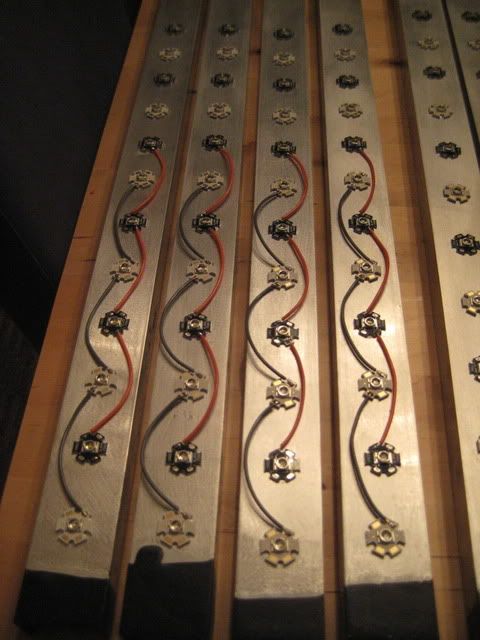
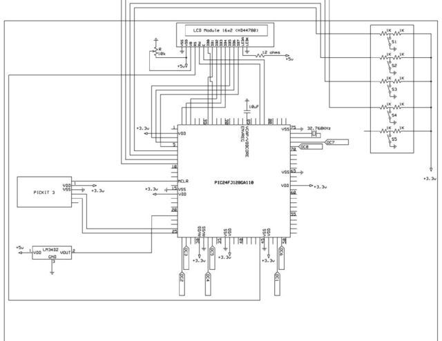
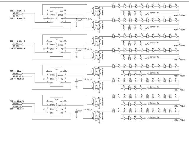
The circuit I have created uses 8 PWM channels to drive 8 banks of 16 LEDs. There is a real time clock and the LEDs simulate sunrise/sunset. In addition I have a temperature sensor which in addtion to the clock output to a backlite LCD screen. To assist others below are my posts on other sites showing the progress/failure I have made. My solution is not perfect and could always be tweaked, but I think it will work.

Circuits postings:

http://www.microchip.com/forums/searchpro.aspx?author=cyrusthevirus&top=50
http://www.edaboard.com/ftopic358016.html
http://www.electro-tech-online.com/electronic-projects-design-ideas-reviews/95410-led-lcd-circuit-design.html
http://www.electro-tech-online.com/general-electronics-chat/103178-testing-mosfet-circuit-without-blowing.html
http://www.electro-tech-online.com/electronic-projects-design-ideas-reviews/95589-5v-3-3v-power-supply-lcd-pic-2.html#post769276
http://www.electro-tech-online.com/micro-controllers/95603-pic24-driving-fets-pwm-signals-leds.html
http://www.electro-tech-online.com/micro-controllers/104407-nfet-parallel-power-supply.html
http://www.dutchforce.com/~eforum/index.php?showtopic=27788
http://www.dutchforce.com/~eforum/index.php?showtopic=30791

In addition to having the sunrise/sunset, I can also independently control the brightness of each string.

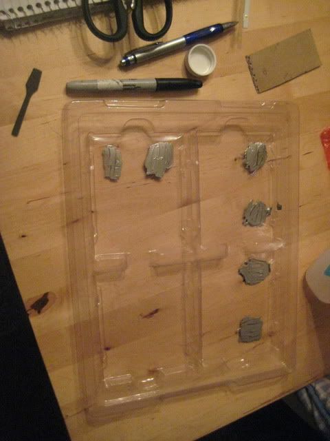
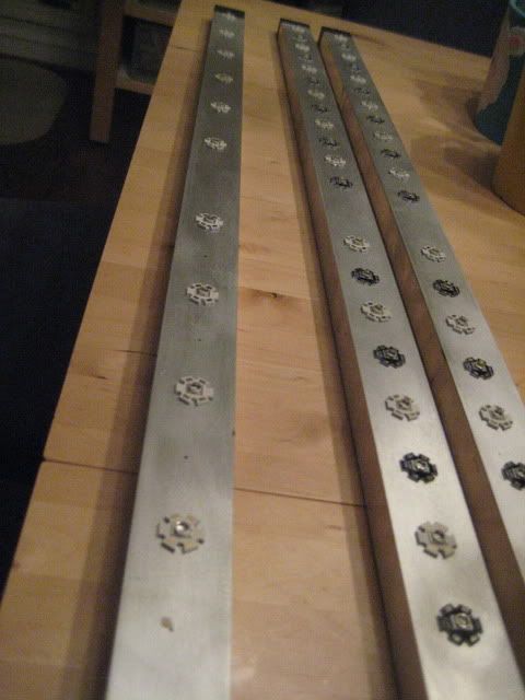
The next steps in the LED are are to build out the actual strings of lights. They are on order so as they arrive over the next few weeks, I will post pictures of my success.


Aquarium.jpg

Aquarium_led.jpg


The tank:
----------------
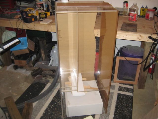
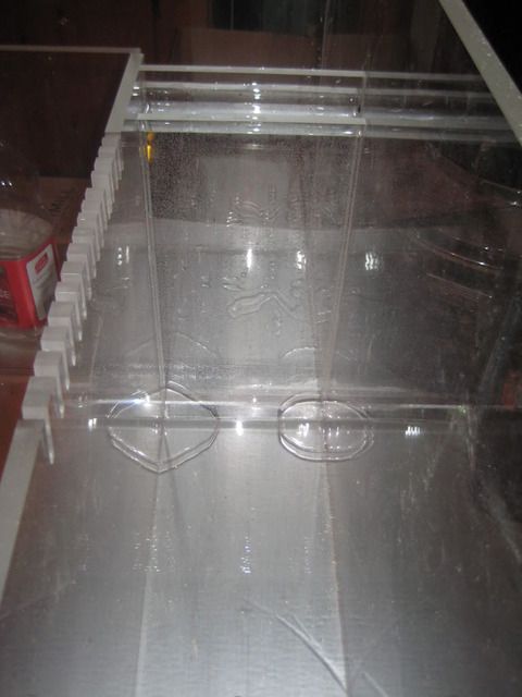
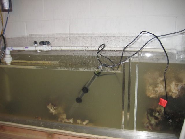
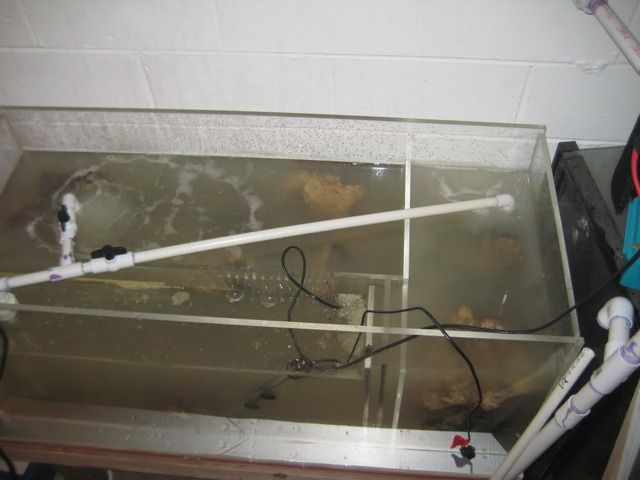
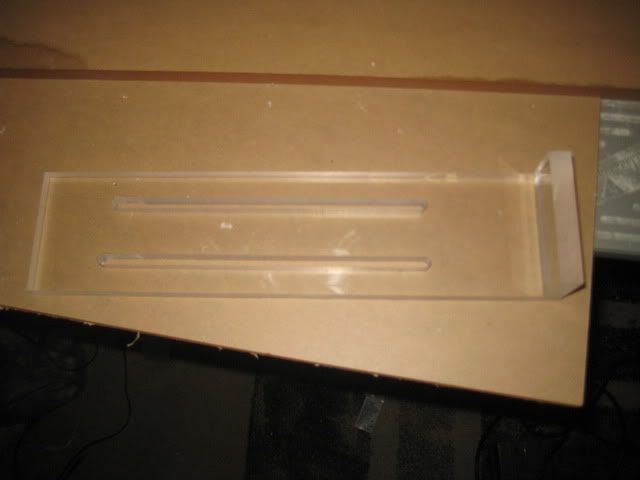
The tank will drain into a sump located in my basement. The sump is an exact replica of the one listed here:
http://www.melevsreef.com/acrylics/sumps/80/80g_sump.html

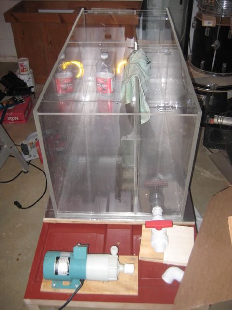
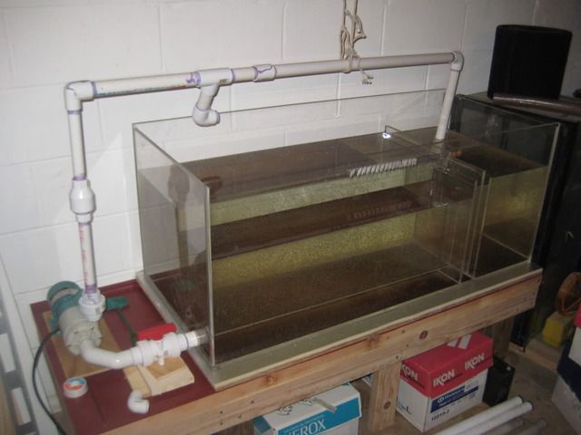
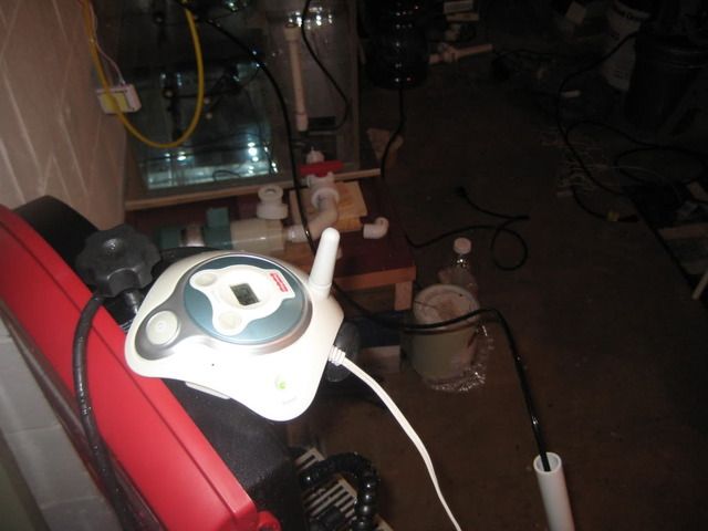
I got lucky and was able to obtain a free pump with the ability to push ~22 feet of head.

I will post some pictures of the sump, now that it has been built and appears to hold water.

That is all for now, I will post more as I continue my progress.
 
I could not find all of the emails with my oder information, but this list should have everything you need.I bought twice of everything so I could have a prototype and a functioning version.

From MPJA.com:
(8 ) 58V @ 1A - Item #15814 PS

From DigiKey:
(1) Temp Sensor - Item #LM34DZ-ND
(8 ) MOSFET N-Channel - Item #IRL520PBF-ND
(1) Silicon Grease - Item #CT40-5-ND
(4) 12VDC Fan - Item #563-1133-ND
(1) 32.768kHz crystal - Item #728-1001-ND
(1) 10k trimpot - Item #T63YB-10K-ND
(5) 10uF capacitor - Item #ECE-A1CKA100
(1) 12ohms 1/4W resistor - Item #CF1/412JRCT-ND
(4) LTC1157 - Item #LTC1157CN8#PBF-ND

From ETGTech.com:
(64) Royal Blue Cree XR-E Item #XREROY-L1-0000-00901

From DealExtreme:
(64) Cree XR-E Q5 - Item #2394

From www.circuitspecialists.com:
(6) Syntax Prototyping Board - Item #PC462905

From Mouser.com:
(1) 22 AWG wire Blue - Item #602-3051/1-100-06
(1) 22 AWG wire White - Item #602-3051/1-100-01
(1) 22 AWG wire Red - Item #602-3051/1-100-03
(1) 22 AWG wire Black - Item #602-3051/1-100-02
(1) 22 AWG wire Green - Item #602-3051/1-100-04
(1) Hantronix LCD - Item #HDM16416L-1-L30S
(1) SchmartBoard - Item #872-202-0011-01
(8 ) 2W 1.2ohms Resistor - Item#594-5083NW1R200J
(20) Phoenix Contact Terminal - Item#651-1729128
(1) Soldering Station/Iron - Item #578-WLC100
(1) Soldering Tip - Item #578-ST-7
(1) Flux Pen - Item #533-2331
(1) Microchip PIC - Item #579-PIC24128GA110IPF
(1) PICKit 3 Programmer - Item #579-DV164131
(1) 1/4 W 1Kohms resistor - Item #291-10K-RC
(1) Soder-Wick - Item #5878-80-3-5

For Prototyping from Mouser.com:
(1) 12" jumpers - Item #872-920-0019-01
(2) PCI Headers - Item #649-78511-236HLF
(1) Mill-Max Headers - Item #575-205030
(2) SIP Sockets - Item #575-8314305010

Dipmicro.com:
For Prototyping:
(1) LEDs - Item #SET-LED5
(1) Breadboard - Item #ZY-204
(2) Jumper Wires - Item #ZY-800
 
Holy Smokes that is one detailed first post. :eek:
First welcome.
Second do I get credit in an electical engineering class for reading this. :D
Finally looks great thanks for posting...I am sure a lot of folks are going to be interested in your progress.
 
First welcome.
Thanks.

Second do I get credit in an electical engineering class for reading this.
I started this about six months ago and new nothing about electrical circuits, so I am hoping for others to be able to use what I have developed without needing a PHD in Elec. Engineering.

I have some pics, just not had a chance to get them off of the camera yet.
 

rodclement

Officer Emeritus
Officer Emeritus
WOW...my head just blew up...where is my brian at...? Paul...where are you...help!!!!

Welcome to the Club! There have been some discussions about DYI leds here before so I am sure this thread is about to become very popular!

Pictures always help for those of us eletronicaly challenged! ;D

Rod
 

redfishbluefish

Officer Emeritus
Officer Emeritus
This is great! I’ll be following along, also having a 90 gallon, albeit five feet long.

Now my only problem is that I understand electrical schematics about as well as understanding Klingon! jIyajbe'

One thing I do understand is money. Could you give us an idea of what we are talking about, $$$ that is? And I’m also looking for those pictures as well.

Thanks and welcome.
 
One thing I do understand is money. Could you give us an idea of what we are talking about, $$$ that is?
Mouser.com: $316.48
DigiKey.com: $99.42
circuitspecialists.com: $16.74
MPJA.com: $159.60
DealExtreme: $280.72
ETGTech.com: $374.40

Total: $1247.36

Two other things to consider, no need to run a chiller, less overall power consumption, bulbs should not need replacing in my lifetime.
 
Thanks for the info...really interested to see how it works out.

Another note since you are new we have a monthly meeting that everyone is welcome to come to. It will be at Rod's house so you get to see our newly elected Prez's tank. :) Plus as a new member you are bound to win at the raffles.
 
To build the refugium, you will need the sizes of 1/2" acrylic:

(4) 48" x 20" (Front, Back, Top and Bottom)
(2) 19" x 20" (Left and Right)
(1) 20" x 15" (Wall of Refugium/Bubble Trap)
(1) 36" x 15" (Wall of Refugium)
(2) 14" x 7" (Bubble Trap)

The best tip I can provide is to make sure you clean all of your edges. I did this with a straight file and chisel. I did not use the pin approach.

Here are some photos:

Sump during the building process
IMG_3042.jpg


Sump on stand w/pump
IMG_3051.jpg


Let's fill it with water and see what happens. Oops a small leak. Nothing a little more weld-on can't fix
IMG_3052.jpg


General setup in basement. I need to work out a better system for the pump while I wait to setup the main tank.
IMG_3055.jpg


Here is my wiring mess. I am working on cleaning it up and will have a non-prototype version next.

IMG_3060.jpg
 
So I was searching on craigslist and came across someone selling LR. I was not ready for it yet but could not pass on the price. The problem was that I had no where to put the rock. I had a sump, but it had no water in it. I also had a tank, but again, no water. So, it was time to connect the RO/DI unit I purchased and start making water.

24 hours later and my first leak of many, I have a full sump of rock and only spilled about 1/2 gallon on the floor. It was my first water leak I was so excited to get the first one out of the way.

Back to the LEDs. The Royal Blues are due to arrive on Wednesday and I am still waiting for the shipping codes from DX. I have been in contact with them every day, so there is hope.

Well, back to creating the circuit boards I need. I wonder if the smoke from the solder is as bad as they say it is? Sometimes, I feel like Mike Rowe on Dirty Jobs.

I added some pices below. The first pic is my water leak early detection system.

IMG_3122.jpg


Just filled it so the water is a little cloudy.
IMG_3125.jpg


Another shot from above:
IMG_3126.jpg
 
The build continues. I received my Royal Blue LEDs, now I am just waiting for the white ones from DX. Advice for everyone do not order from them, their customer service is terrible, I guess you get what you pay for.

I am also going to add a DIY pH meter and DIY salinity meter. I completed my research on them and they seem pretty easy. I think I can build the pH meter for about $35-40 including the probe and the salinity for about $100 including the probe.

After posting a question about the state of heaters, looks like I may add a relay for controlling the heater.

I will upload more pics once I get them off the camera.
 
A couple of pics from the past week:

Two control circuit boards for 8 banks of LEDs:
IMG_3128.jpg


Microcontroller wires coming from SchmartBoard:
IMG_3156.jpg


One week later, the sump is much cleaner:
IMG_3157.jpg
 
Re: 90g DIY LED w/ sunrise/sunset/moonlight/water monitor

So the sunrise/sunset controller continues to expand. I just completed the circuits for the DIY pH, ORP and salitity meters. I orders several so I could monitor both the sump and maybe a holding tank of water for water changes. They should be in within the next week. Looks like I can create all three types of monitors for less than $40 each.

Let's hope I can keep the momentum going.
 
Well I was ready to start building until I decided to greatly increase the scope of the project. Now I am waiting on my probes to ship from China. I also ordered some "U" channel aluminum to use as a heat sink. Even with shipping it was 25% of the cost of Home Depot.

Waiting for a couple of parts, and then I will post some pics.
 
pH/Salinity and ORP circuit boards have been soldered. They are below. Now I am just waiting on the probes, They should ship next week. I received all of the LEDs, the U chennel and the fans, now I just have to find the time to build.

pH/ORP before soldering:
IMG_3198.jpg

pH/ORP after soldering:
IMG_3252.jpg


Salinity before soldering:
IMG_3197.jpg

Salinity after soldering:

IMG_3254.jpg
 
Okay so I have been very busy. Here are some pictures of the LED setup for my build:

Tracing the fan for the hole:
IMG_3258.jpg


Hole cut rubber gromets in place
IMG_3257.jpg


The fan, only 14 dBA at 12VDC
IMG_3259.jpg


The fan mounted on reflector:
IMG_3256.jpg


All four fans mounted and placed back in light hood.
IMG_3265.jpg


Now on to the LEDs.
 
It's LED glue time:

Mix up the epoxy:
IMG_3277.jpg


Begin laying them out and attaching them. Remember to work in small batches, you only have 5 minutes before the epoxy sets.
IMG_3275.jpg


And with the miracle of the Internet, they are all attached and some wired. (2) 3' strips and (4) 4' strips.
IMG_3281.jpg


Mostly wired up:
IMG_3279.jpg


I ordered the PCBs for the constant current circuit today so I will get 37 of them in a week. It was cheaper to get 37 than the 8 I really need. This circuit will take a 58V 1A power supply and drive 16 LEDs either with or without a PWM signal. The overall cost for the DIY driver falls to less than $15.
 
Sorry for all of the updates, I have not had the time to post.

While I wait for the PCB to drive the LEDs, I decided to move on to my ATO.

The heart of the ATO are two 12 VDC solenoids which run at 1.7A each. Two are used for redundancy:
IMG_3304.jpg


IMG_3324.jpg


These are wired to a relay which controls an upper and lower float switch. The low switch opens the solenoids and the upper switch closes them. That way I can run enough gallons to prevent TDS creep.

The relay:
IMG_3325.jpg


The DIY hanger:
IMG_3303.jpg


The DIY clips for the floats:
IMG_3309.jpg


Here it is all put together. For snail guards, I used new pill bottles. They are free just ask your local CVS for two.
IMG_3321.jpg


On the right of the picture you will notice a mechanical float. The is the final failsafe. One thing I found out is the model I bought from the filterguys already had the switch built in. All I need to purchase was the float valve. I which I realized this before I made my purchase of a mechanical float kit.

Here is a shot from above:
IMG_3323.jpg
 
Top